

TOPIC 2: ELECTRICITY
In this section we will take a closer look at some other common components in circuits, and learn a bit more about how they function.
Light bulbs used in laboratory circuits (correctly called filament lamps) have a very thin wire inside. This wire glows white hot when a current passes through it, producing heat and light.
A wire normally follow Ohm's Law - the current through it is proportional to the voltage applied. However the thin wire in a lamp gets so hot that the resistance increases. The current still increases with voltage, but - as you can see on the graph below in figure 1 - the line becomes curved. It no longer follows Ohm's Law.
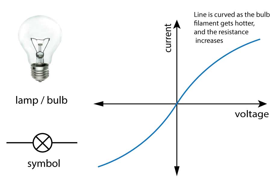
Figure 1. I~V graph for lamps
This graph shows a positive and negative voltage and current. A negative current simply means current flowing in the opposite direction through the lamp. Notice that the graph is symmetrical. This means the bulb has the same properties regardless of the direction of current.
Diodes are very clever components that work like one way gates. Current can only go through one way. They work a bit like a normal door at home that opens one way only. (not a 'swing' door).
To open a door, you need a small push to get it open - then lots of people can 'flow' through the doorway. However if you push on the door from the other side, it will not open, and no one can go through.
Similarly for a diode, you need a small forward push (a voltage or p.d. across the diode) to get it to 'open' or conduct electricity. If the voltage is reversed, virtually no current flows - the resistance is extremely high.
The diode conducts in the direction of the arrow shown in the symbol, as shown below.
Light Emitting diodes (LEDs) are simply diodes that emit light when a current flows through it. Otherwise it behaves (almost) exactly like a normal diode. You can buy LEDs in many different colours, and as they are getting more and more efficient, they are becoming more common place and used widely for household and office lighting. They are also used in T.V. sets, traffic lights, power indicators and many more applications.
| Diode |  Current → |
 |
| LED (light emitting diode) |
 |
 |
| *Note: Diode symbols may have circles around them for AQA. | ||
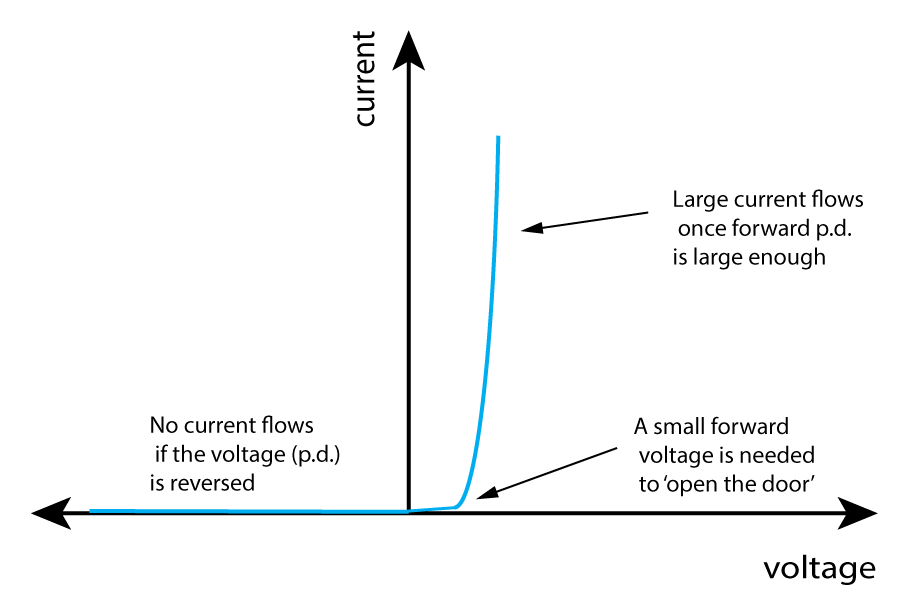
Figure 2. I ~ V graph for diodes
You will need to learn to recognise and draw the graph above.
All LEDs are usually connected in series with a protection resistor - as you can see from the graph above, they only need a small voltage, and for most of them the maximum current is still quite low as they are so efficient.
A thermistor is a heat sensitive resistor. As the temperature of the surroundings increases, the resistance decreases.
An LDR is a light dependent resistor. As the light level increases, the resistance decreases.
For both of these devices, the resistance change is in reverse to the quantity being sensed, so for the thermistor, it has a higher resistance when the temperature is low.
These sensors are very useful in circuits that are needed to detect changes in the environment - for example to turn on street lights at night, and to turn on the heating at home when it gets too cold. A thermostat is a device that switches on or off at a certain temperature to control heating in homes and offices, and typically includes a thermistor.
| Thermistor |  |
temperature ↑ = resistance ↓ |
| LDR (light dependent resistor) |
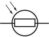 |
light level ↑ = resistance ↓ |
Both of these components can be included in simple circuits, and you will be asked to describe and explain what is happening. Have a go at these questions to check you understand the rules above:
Questions:
1. An LED is connected in series with a 6V cell and a thermistor.
a) The circuit diagram should look like this. Note that the L.E.D. arrow must be in the direction of current flow from positive to negative.The symbol for the LED can have a circle around it.

b) As the temperature increases, the resistance of the thermistor decreases. This means that the current will increase in the circuit, and the LED will become brighter.
(Remember that this is an 'explain' question, so you need to use physics to explain carefully what is happening, not just state the final outcome).
2. The following circuit is constructed with a fixed resistor, an LDR and various meters:
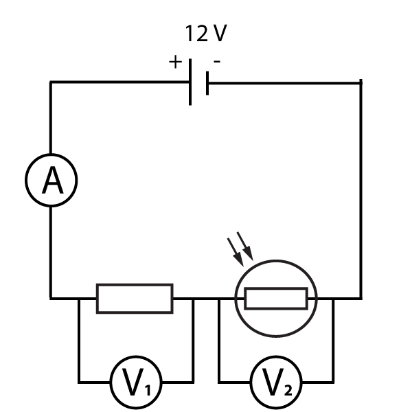
The light level in the room slowly increases. Explain what happens to the readings of:
This question is hard because it involves knowing about the components in detail, as well as understanding the rules for a series circuit from section 2.3.
a) As light falls on an LDR, the resistance decreases. This means the total resistance of the two components also decreases (The total is the sum of the two resistors - the ammeter can be ignored).
If the total resistance decreases, then the current increases as shown on the ammeter.
b) We know that for the fixed resistor, V = I x R
If the current I round the circuit increases, and R is fixed, then V1 must increase.
c) The voltage in a series circuit is shared between the components.
If V1 increases, then V2 must decrease - the LDR gets a smaller share of the voltage and has a smaller p.d. across it.
As the name implies, a variable resistor is simply a resistor that can change value. These are often changed by turning a knob, as found in light dimmer switches or old-style radio volume controls.
| Variable Resistor |  |
Here are a few other common components that you may come across although they are not essential for this syllabus:
| A heater (or heating element) |  |
As found in room heaters, hair dryers and toasters. |
| A motor |  |
As found in toy cars - uses electricity to turn the wheels. |
| A generator |  |
Generates electricity by spinning the generator, as found in wind turbines. |
| A loudspeaker |  |
Produces sound waves from electrical signals. |
| A bell |  |
As found on old door bells and fire alarms. |
Investigating the I-V characteristics of components.
In this practical, you need to be able to follow a circuit diagram and set up the circuit needed to measure the current and potential difference across resistors, diodes and filament lamps. You can then use your results to produce the familiar I-V characteristics as shown in the graphs on this page.
A typical circuit will look like this (as shown on the previous page on resistors):

Starting with the power supply set at zero volts output, increase the voltage up to a maximum of 12 V, usually in 1 V steps. Note that many power packs have really unreliable outputs - you should use the readings on the voltmeter, not the setting on the power pack!
After recording these readings, you can reverse the power pack connections
to generate negative values, and then plot a graph to show the full I-V characteristics.
Now test your understanding using these quick, 10 minute questions on this topic from Grade Gorilla: